 |
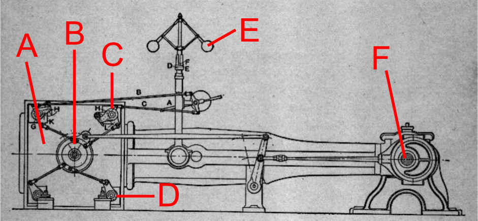
Typical Corliss Engine Layout A - Steam Cylinder B - Wrist plate / Valve Gear C - Steam Inlet Valve D - Steam Exhaust Valve E - Governor F - Crankshaft / Valve Gear Eccentric |
Corliss Steam Engine Basics
Both of the large stationary steam engines we have at this time for our display are of the Corliss engine type. The Corliss engine type is characterized by the arrangement of the steam inlet and exhaust valves in the cylinder. For a Corliss engine there are two inlet valves at each end of the cylinder at the top and two exhaust valves at each end of the bottom of the cylinder. However, there are rare examples where the position of the inlet and exhaust valves may be reversed. The Corliss valve style is also known for the unique inlet valve releasing mechanism. There were many types of release gear developed but most followed the same principle. Regulation of this kind of engine is accomplished by the variable steam cutoff this valve gear provides. Depending on the load on the engine steam is admitted to the cylinder for more or less of the stroke of the piston. Under heavy loads steam may be admitted for nearly the full travel of the piston while at lighter loads steam will be admitted for only a fraction of the piston travel. In this way the expansive power of the steam is maximized while minimizing the steam consumption. Pictured below is a diagram illustrating a typical Corliss steam engine layout.
|
Typical Corliss Engine Layout A - Steam Cylinder B - Wrist plate / Valve Gear C - Steam Inlet Valve D - Steam Exhaust Valve E - Governor F - Crankshaft / Valve Gear Eccentric |
|
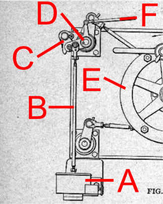
What makes a Corliss valve equipped engine unique is the variable time the inlet valve is closed during the piston travel. As the piston travels the length of the stroke, a latch on the valve gear reaches a cam which is positioned by the engine governor. When the latch reaches this cam the inlet valve is released. On the end of the valve is an arm attached to a rod linking the valve to the dashpot. The dashpot serves two purposes: First, as the valve is initially opened a vacuum is formed which is used to pull the valve closed quickly at the moment it is released. Second, as the valve reaches the closed position the air in the dashpot is compressed at the last moment and provides a slight cushion to the valve. This prevents the valve from "slamming" shut. The illustration below shows the relationship of the various valve gear components. |
|
|
Typical Corliss Valve Gear A - Dashpot B - Dashpot Link Rod C - Inlet Valve Latch D - Inlet Valve Stem With Dashpot Arm E - Wrist plate / Valve Gear F - Governor Link Rod
|
 |
Corliss Valve Gear Operation:
The sequence begins with the piston at one end of the cylinder. At this point, the exhaust valve in the left end of the cylinder is opened and the steam inlet valve in the right end of the cylinder is opened (fig. 1 below). When the steam enters the cylinder it pushes the piston toward the left end of the cylinder. Part way through the stoke the right inlet valve is closed and the steam in the cylinder continues to expand and push the piston (fig. 2 below). When the far end of the stoke is reached the valve gear rotates the exhaust valve in the right end of the cylinder open as the inlet valve in the left end of the cylinder is opened (fig. 3 below). This allows the steam to the right of the piston to escape the cylinder as live steam now pushes on the left side of the piston. Part way through the return stroke the inlet valve closes and the expansion of the steam pushes the piston to the end of its travel. At this point the cycle begins again.
Figure 1 |
Figure 2 |
Figure 3 |
Figure 4 |